
Methodology
- Nu'man Kamil
- Aug 19, 2020
- 3 min read

Updated: Apr 29, 2021

3.1 Introduction
It takes a basic understanding of electricity and creativity to create the proposed food dispenser. In this chapter will be discussed about the critical methods and reasonings in developing an Automated Food Dispenser. Besides, the components used in this proposed project also will be further introduced as well as the data collected in term of the block diagram and flow chart also will be included.
3.2 Data Source/Material
3.2.1 Switching Power Supply AC to DC 12V
Switching power supply can convert and regulates the electrical supply from AC to DC. It is known as SMPS provides needed output voltage instead of a standard linear method with the help of semiconductor switching techniques. Higher efficiencies, lighter weight, longer hold times and the capacity to accommodate broader input voltage ranges featured in switching power supplies.

Figure: 3.1
3.2.2 Arduino
The Arduino Uno is an 8-bit Atmega328 microcontroller-based microcontroller module. It comes with a USB interface, 14 digital I / O ports, and 6 analogue input pins that can be attached to the outer circuit. For PWM production; six pins from the I / O ports can be used. Using the IDE (Integrated Development Environment) program, the code passed to the controller and C or C++ languages are most likely used.

Figure 3.2
3.2.3 Radio-Frequency Identification (RFID)
The module can support I2C, SPI, and UAR; which are the latest hardware interfaces people use in microcontroller development and commonly shipped with a key fob and an RFID card. Widely used in attendance systems and other applications for person/object recognition

Figure 3.3:
3.2.4 Motor Driver
The motor driver is the device that makes the stepper motor moves as the instruction given. The low voltage input comes from the microcontroller or microprocessor and controls an actual motor that requires a high voltage input. For instance, Arduino has an operating voltage of 5V, but it needs a 12V supply to operate the stepper motor. In this proposed project, the motor driver controls the direction of the stepper motor either it is clockwise or anti-clockwise and can achieve it by using H-bridge technique.

Figure 3.4:
3.2.5 12V Stepper Motor
Stepper motor is a brushless motor that divides a complete rotation into several steps. Although it is a small low power unit, the stepper motor is widely used mainly in automation systems. The stepper motor is, therefore cheap, durable and very easy to place. Stepper motor operates with 12, 24, 72, 144, 180, 200 steps per revolution. The regular stepper motors would have a phase angle of 1.8 degrees with 200 steps per revolution.

Figure 3.5:
3.2.6 AutoCAD
AutoCAD is popular software that engineers and architects usually use to design anything from core tools to things as complex as construction and bridges. It provides the means to draw stuff to scale. By obtaining this resource on the system, the process becomes exponentially simpler and quicker. It also allows engineers to shift the blueprint into reality.

Figure 3.6
3.2.7 Arduino IDE
Any device that uses Arduino or any other smart electronic circuit must be a source code built into the system so that the hardware can properly monitor any job or operation. Arduino IDE is used in this project as it is very suitable for inexperienced programmers or people who are still new to coding. It functions as a code developer that is transferred to the Arduino UNO and controls the load.

Figure 3.7
3.3 Research Design
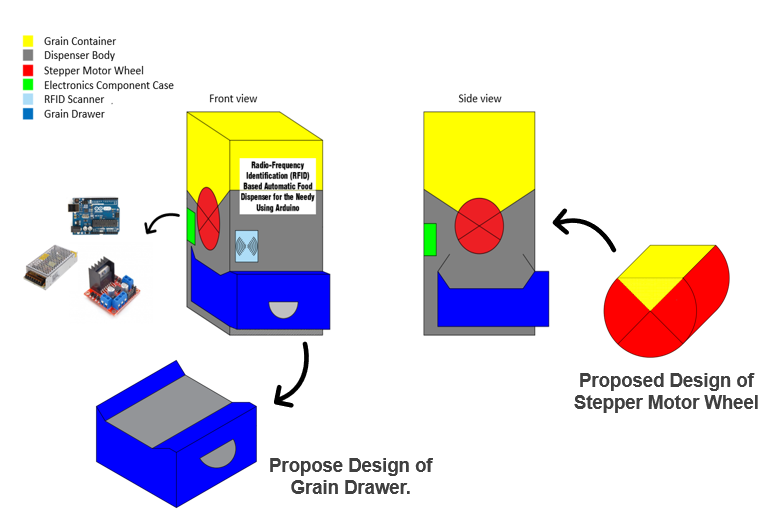
Figure 3.8:
3.4. Data Collecting Technique
3.4.1 Block Diagram

3.4.2 Flow Chart

3. 5 Summary of the chapter
In summary, the component of the proposed project and the function listed. Hopefully, all of the electronics components will fit and functioning well. The proposed design of the project also designed early to get better visual on how this project will look likes. Block diagram and flow chart will help in planning the step and components of the proposed project.


Comments